Introduction to ESP8266
Struggling to get ESP8266 connected? In this series of articles I’ll share my experience with ESP8266 to help you get over the struggle.
What is ESP8266 and why should you use it?
The ESP8266 Wi-Fi Module is a chip which contains an independent system with an integrated TCP/IP stack that gives the Micro-controller access to your Wi-Fi network.
 |
It is used to host applications as well as for many other Wi-Fi functions. These modules are pre-programmed with firmware which includes a set of AT commands. Coded AT commands will give Wi-Fi connectivity to the prototype
Power consumption is comparatively low and the module can also be used under a temperature range of 40°C to +125°C
 Most importantly it’s low cost. But it does a great amount of work for you. It’s impressive how it adds Wi-Fi functionality to your project prototype using a simple UART connection.
Guess what? It is compatible with Arduino IDE! I was much interested in Arduino coding when I started doing my first IOT project and compatibility of ESP8266 with Arduino IDE was a great reason behind my selection.
Don’t get lost
Well, I got all lost with the choices available in the market cause I had no guidance as a beginner. I ended up buying both the versions ESP-01 and ESP-07. After spending some time on learning the 2 versions, I decided on ESP-01, because I found it easier to work with than ESP-07 with the knowledge I had gained. If you’re totally new to this area of study I’d recommend you to use ESP-01.
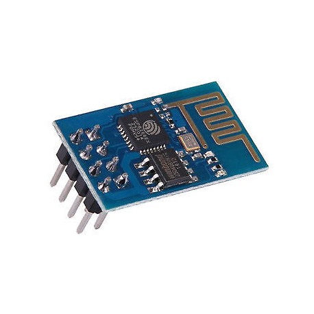
ESP-01 is one of the first ESP8266 modules delivered to customers. It’s the cheapest and the smallest module available and it smoothly runs with the Arduino IDE.
 |
| Module Variants | Img src : web-engineering.info |
ESP-01 is one of the first ESP8266 modules delivered to customers. It’s the cheapest and the smallest module available and it smoothly runs with the Arduino IDE.
Well, it might have a slight disadvantage such as not having access to all the pins, but this might only arise when doing complex projects.
(Basically, selection of ESP8266 depends on what functionality it should perform in your project. According to what I’ve studied so far, ESP-07 / ESP-12 would be the best if you’re trying to make your own PCB with Wi-Fi connectivity.)
Understanding ESP8266
It works under a voltage of 3.3V. But it’s possible to supply voltage up to 3.6V. It consumes 100mAmp current while having a Maximum Driving Power (IO) of 12 mA.
 |
| Pin Definitions | Img src : pixhawk.org |
This has 8 pins.
Out of these VCC, RST, CH_PD and GND and pins are used in connections but are not identified as I/O pins.
- VCC uses power in the range of 3.0 – 3.6V
- RST-Used at 3.3 V for normal operations and 0V to reset the chip.
- CH_PD, performs the functionality of enabling the chip. Can also be used for auto reset at some instances.
- GND should be connected to Ground of Arduino.
GPIO0, GPIO2, TX and RX are used in operation with pre-assigned functions, as I/O pins.
- GPO0 and GPIO2 which are general purpose digital ports, are responsible for the mode in which the module starts up and will ensure that the module starts up correctly.
- TX and RX are used in programming the module as well as for Serial I/O.
Important points to consider before going into Implementation
- DO NOT use 5V. The module’s pins only allow 3.3v from the Arduino board.
- Baud Rate should be changed according to the firmware version as either 115200bps (default) or 9600bps.
- Carriage return should be selected as NL and CR for later versions of ESP8266.
Now that you have a basic understanding of what the ESP8266 module is, let’s move on to a simple practical application of the device.
Good article. Keep up the good work
ReplyDelete